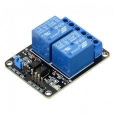
The pins are marked on the PCB:-
- GND – Connect 0V to this pin.
- IN1 – Controls relay 1, active Low Relay will turn on when this input goes below about 2.0V
- IN2 – Controls relay 2, active Low Relay will turn on when this input goes below about 2.0V
- VCC – Connect 5V to this pin. Is used to power the opto couplers
Specification:-
- High current relay, AC250V 10A, DC5V 10A
- 2 LEDs to indicate when relays are on
- Works with logic level signals from 3.3V or 5V devices
- Opto isolation circuitry